Cutting Tool of Lathe Machine: 9 Powerful Types Explained
 Kamran Liaquat Ali
- posted on
- No Comment

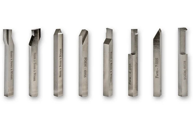
A cutting tool of lathe machine removes material from a rotating workpiece to create the required diameter, length, taper, groove, thread, face, or internal surface. Tool material, geometry, setup, speed, feed, depth of cut, workpiece material, rigidity, coolant, and machine condition all determine accuracy, surface finish, productivity, and tool life.
Table of Contents
This evergreen guide explains nine major tool types, tool geometry, materials, inserts, tool holders, cutting parameters, wear, troubleshooting, safety, and selection. For wider context, visit our engineering and manufacturing guide, which connects machining with manufacturing processes, materials, automation, quality, and industrial systems.
What Is a Cutting Tool of Lathe Machine?
A cutting tool of lathe machine is a wedge-shaped device positioned against a rotating workpiece. Relative motion and force cause material to shear into chips. In conventional turning the workpiece rotates in a chuck, collet, faceplate, or between centers while the tool moves longitudinally, radially, or along a programmed path.
Manual lathes use hand-controlled feeds and tool posts. CNC turning centers control axes, spindle, tool changes, coolant, and cycles through a program. The cutting principles remain similar, but CNC systems demand consistent inserts, controlled offsets, secure tool holding, and reliable chip management. Our CNC machining guide explains the wider digital manufacturing process.
How a Lathe Cutting Tool Removes Material
The cutting edge penetrates the workpiece and compresses material ahead of it. The material shears along a zone and flows over the rake face as a chip. Friction and plastic deformation produce heat. Some heat leaves with the chip, while the rest enters the tool, workpiece, and cutting fluid.
Cutting force has tangential, feed, and radial components. Excessive force can deflect the workpiece, tool, holder, or machine. Deflection changes dimensions and may cause chatter. A stable process uses the shortest practical tool overhang, secure workholding, suitable geometry, and parameters matched to machine power and rigidity.
9 Powerful Types of Lathe Cutting Tools
1. Turning Tool
A cutting tool of lathe machine used for turning reduces the outside diameter as it feeds parallel to the workpiece axis. Roughing tools remove larger amounts of material, while finishing tools use lighter cuts to achieve final size and surface. Lead angle, nose radius, chip breaker, insert grade, and feed influence performance.
2. Facing Tool
A cutting tool of lathe machine used for facing moves across the end of a rotating part to create a flat surface perpendicular to the axis. Cutting speed decreases toward the center because surface velocity depends on diameter. Correct tool position is important to avoid leaving a central pip or rubbing below center.
3. Parting Tool
A cutting tool of lathe machine used for parting uses a narrow blade or insert to separate a finished component from bar stock. Rigidity, center height, alignment, chip evacuation, and controlled feed are critical. Deep parting operations can trap chips and coolant, increasing heat and breakage risk.
4. Grooving Tool
A cutting tool of lathe machine used for grooving creates external, internal, face, or undercut grooves. Insert width and corner radii must match drawing requirements. Some tools can plunge directly and then turn sideways, but side cutting requires suitable geometry and manufacturer guidance.
5. Threading Tool
A cutting tool of lathe machine used for threading forms a helical profile as tool feed synchronizes with spindle rotation. The insert profile must match thread form, pitch range, and internal or external application. Multiple passes distribute cutting load. Correct infeed method, relief, alignment, and final inspection prevent poor flanks or incorrect pitch diameter.
6. Boring Tool
A cutting tool of lathe machine fitted to a boring bar enlarges or finishes an existing hole. Because the bar extends inside the workpiece, rigidity is lower than external turning. Large diameter, short overhang, proper insert geometry, and vibration-damped bars improve stability. Chip evacuation and tool clearance must be confirmed.
7. Form Tool
A cutting tool of lathe machine used as a form tool produces a specific contour through a direct plunge or short movement. It can create radii, beads, chamfers, or combined features quickly. Wide contact creates high force and chatter risk, so form tools need rigid setups and realistic speeds.
8. Chamfering Tool
A cutting tool of lathe machine used for chamfering produces a bevel at an edge, improving assembly, removing sharpness, or preparing a thread. Standard turning tools may create chamfers when oriented correctly. Size should be measured because hand deburring can produce inconsistent results.
9. Knurling Tool
A knurling tool normally displaces material rather than cutting it. Hardened wheels press a straight, diagonal, or diamond pattern into the rotating surface for grip or controlled diameter. Scissor-type holders reduce radial load compared with simple bump knurling. Wheel pitch, diameter tracking, pressure, lubrication, and alignment affect pattern quality.
Single-Point Cutting Tool Geometry
Understanding the cutting tool of lathe machine requires knowing its surfaces and angles. The rake face guides chip flow. Flank faces provide clearance from the newly machined surface. The major and minor cutting edges meet at the nose, which may have a radius.
- Rake angle: influences cutting force, edge strength, heat, and chip flow.
- Clearance angle: prevents flank rubbing while retaining adequate support.
- Lead or entering angle: distributes forces and changes chip thickness.
- Inclination angle: influences chip direction and edge engagement.
- Nose radius: strengthens the corner and can improve finish, but an excessive radius may promote chatter.
Positive geometry generally cuts with lower force and helps on low-power machines, slender parts, or soft materials. Negative geometry provides a stronger edge and can use double-sided inserts, but it needs greater force and rigidity. The best choice depends on the complete application.
Cutting Tool Materials
High-Speed Steel
High-speed steel is tough, relatively inexpensive, and easy to grind into custom shapes. It suits low-speed work, interrupted cuts, small batches, form tools, and educational workshops. Its hot hardness and wear resistance are lower than carbide, limiting cutting speed.
Cemented Carbide
Carbide combines hard particles with a metallic binder. It supports higher speeds and broad industrial use. Coated carbide grades add layers that resist wear, heat, diffusion, and adhesion. Grade selection balances hardness and toughness for steel, stainless steel, cast iron, nonferrous alloys, or heat-resistant materials.
Ceramic and CBN
Ceramic tools retain hardness at high temperature and can machine cast iron or certain hardened and heat-resistant materials at high speed. Cubic boron nitride is especially useful for hardened steels and selected cast irons. Both materials require suitable stability because edges can be less tolerant of impact.
Diamond Tools
Polycrystalline and single-crystal diamond provide exceptional hardness and finish on aluminum alloys, copper, composites, plastics, and abrasive nonferrous materials. Diamond is generally unsuitable for ferrous materials at high cutting temperatures because chemical wear can accelerate.
Indexable Inserts and ISO Shapes
For a cutting tool of lathe machine, indexable inserts provide multiple cutting edges and repeatable geometry. Common shapes include round, square, triangular, rhombic, and trigon styles. Shape influences corner strength, accessibility, lead angle, and available edges. A strong square insert may suit roughing, while an acute diamond shape reaches complex profiles with less corner strength.
Insert codes identify shape, clearance, tolerance, hole or chip-form features, size, thickness, and nose radius. Grade and chip-breaker design are usually selected separately. Manufacturer recommendations provide a useful starting point, but actual results must be verified on the specific workpiece and machine.
Tool Holders, Center Height, and Overhang
A tool holder locates each cutting tool of lathe machine and transfers forces into the turret or tool post. It must match insert style, approach direction, shank size, coolant delivery, and machine interface. Dirty or damaged seating surfaces can move the insert or create runout.
The cutting tool of lathe machine should be set at the intended center height. A tool above or below center changes effective geometry and may cause rubbing, poor facing, dimensional error, or breakage. Parting and threading tools also require accurate perpendicular alignment.
Overhang should be minimized. A boring bar extending farther than necessary behaves like a flexible beam and is prone to chatter. Tool blocks, sleeves, and clamps should support the holder securely without damage or contamination.
Cutting Speed, Feed, and Depth of Cut
Cutting speed is the surface velocity between workpiece and edge. Spindle speed is calculated from cutting speed and workpiece diameter. Feed is tool advance per revolution, and depth of cut is the radial material removed in one pass. These parameters interact with chip thickness, force, temperature, finish, tool life, power, and cycle time.
Start with tool-supplier data for the workpiece material, operation, grade, and geometry. Reduce aggressiveness for weak workholding, interrupted cuts, poor machine condition, or long overhang. Increase parameters only after chip form, force, vibration, temperature, dimensions, and insert wear demonstrate a stable process.
For finishing, feed and nose radius strongly influence theoretical surface roughness. A smaller feed often improves finish, but feeding too lightly can cause rubbing, work hardening, or built-up edge. The finishing allowance must be large enough to cut below the damaged surface from roughing.
Chip Control and Cutting Fluid
Long continuous chips from a cutting tool of lathe machine can wrap around the workpiece, damage the surface, block coolant, or endanger operators. Chip breakers shape and curl chips according to feed, depth, material, and geometry. A chip breaker used outside its operating range may fail to break chips even when the insert is sharp.
Cutting fluid may cool and lubricate a cutting tool of lathe machine, flush chips, protect surfaces, and improve tool life. Application should reach the cutting zone at suitable pressure and flow. Some tools and materials perform well dry; others benefit from consistent flood or high-pressure delivery. Intermittent coolant on a very hot brittle insert can create thermal cracking.
Tool Wear and Failure Modes
- Flank wear: gradual wear on the clearance face that affects size and finish.
- Crater wear: a depression on the rake face caused by chip contact and heat.
- Notch wear: localized damage at the depth-of-cut line.
- Built-up edge: workpiece material adheres to the edge and changes geometry.
- Chipping: small fractures caused by impact, instability, inclusions, or excessive load.
- Thermal cracking: repeated temperature cycles create cracks across the edge.
- Plastic deformation: the edge changes shape under excessive heat and stress.
- Catastrophic fracture: sudden failure from overload, collision, or unsupported geometry.
Cutting tool of lathe machine life criteria should match the process. Waiting for complete breakage risks scrap and damage. Fixed replacement intervals are simple but may waste useful life. Condition-based decisions can use wear inspection, load, vibration, acoustic signals, dimensional trends, surface finish, or chip changes.
Selecting the Right Cutting Tool
- Identify workpiece material, hardness, condition, and abrasiveness.
- Define operation, geometry, tolerance, finish, and production quantity.
- Review machine power, speed, rigidity, turret interface, and coolant capability.
- Evaluate workholding, part slenderness, interrupted cuts, and access.
- Select tool type, holder, insert shape, grade, coating, chip breaker, and nose radius.
- Choose starting speed, feed, and depth from reliable application data.
- Run a controlled trial and inspect chips, wear, dimensions, finish, and stability.
- Document approved tools, offsets, parameters, and replacement criteria.
The cheapest insert is not always the lowest-cost cutting tool of lathe machine. Tool cost must be compared with cycle time, edge count, machine downtime, scrap risk, consistency, and operator effort. A premium tool that runs reliably may reduce total part cost.
Common Turning Problems and Solutions
Chatter
Chatter creates waves, noise, poor finish, and tool damage. Shorten tool and workpiece overhang, improve clamping, check bearings and gibs, adjust speed, change feed or depth, and select geometry that reduces force. Changing speed often moves the process away from resonance.
Poor Surface Finish
Check insert wear, built-up edge, feed, nose radius, runout, rigidity, chip scratching, material condition, and coolant. A new insert will not correct loose workholding or machine vibration.
Dimensional Drift
Tool wear, thermal growth, workpiece stress, fixture movement, measurement error, and machine condition can shift size. Use reliable inspection, controlled offsets, warm-up practices, and root-cause analysis rather than repeated unexplained compensation.
Insert Breakage
Investigate collisions, excessive load, weak geometry, unsupported corners, interrupted cuts, chip recutting, poor seating, and incorrect center height. Replacing the insert without finding the cause can repeat the failure.
Lathe Tool Safety
Hazards include rotating chucks, projecting stock, entanglement, sharp chips, hot surfaces, broken tools, coolant mist, and heavy workpieces. Guards, safe procedures, training, eye and face protection, chip tools, secure workholding, and controlled clothing are essential. Never remove chips by hand or reach across rotating work.
The OSHA machine-guarding guidance describes protection from rotating parts, points of operation, flying chips, and sparks. Before setup, maintenance, or clearing a jam, follow authorized isolation procedures appropriate to the machine and workplace.
Grinding and Reconditioning Lathe Tools
A cutting tool of lathe machine made from high-speed steel can be ground for turning, facing, threading, grooving, or forming. Grinding must create correct rake, clearance, edge angles, and nose radius without overheating the steel. Frequent cooling, a suitable wheel, light pressure, eye protection, and a secure tool rest improve safety and consistency.
Every cutting tool of lathe machine should be inspected after grinding. The edge should be sharp and free from burns, cracks, chips, and unintended facets. A small hone can strengthen and smooth the edge. The finished geometry should be checked against an approved template or measuring method rather than judged only by appearance.
Indexable inserts are normally replaced or indexed instead of ground by the user. Regrinding an insert can remove coating, change geometry, and make the clamping system unsafe. Follow the tool supplier’s instructions and control any approved reconditioning process.
Tool Setup and First-Part Verification
Before production, confirm that each cutting tool of lathe machine matches the setup sheet, holder, insert, grade, orientation, and station. Clean the insert pocket, seat, shim, screw, and holder. Tighten components with the correct method and ensure the edge is clear of the chuck, jaws, tailstock, and adjacent tools.
Set the cutting tool of lathe machine at the correct center height and minimize overhang. Verify work offsets, geometry offsets, nose-radius compensation, spindle direction, speed limits, and coolant. A dry run or simulation is useful, but it does not replace controlled prove-out at the machine.
The first part should be inspected at defined stages. Measure critical diameters, lengths, grooves, threads, runout, and finish. Record any approved offset adjustment. If a cutting tool of lathe machine behaves differently from the validated setup, stop and determine the cause before releasing the batch.
Tool Storage and Process Documentation
A cutting tool of lathe machine should be stored so its edge, holder, identification, and mating surfaces are protected. Mixed inserts, loose screws, corrosion, and damaged pockets create setup errors. Kits or controlled tool cabinets can keep the approved components together.
Process documents should identify the cutting tool of lathe machine by holder and insert code, grade, chip breaker, nose radius, station, offsets, parameters, coolant, and replacement criteria. Photographs can support instructions but should not replace part numbers and controlled drawings.
Tool-life records help compare suppliers, materials, machines, and batches. Record the reason for replacement rather than only edge count. A cutting tool of lathe machine that fails through chatter needs a different corrective action from one that reaches a normal wear limit.
Frequently Asked Questions
Which cutting tool is most common on a lathe?
An indexable single-point turning tool is common in production because inserts provide repeatable edges and grades for many materials. High-speed-steel tools remain useful for custom shapes and lower-speed work.
What is the best tool material?
There is no universal best material. Carbide covers many applications, while high-speed steel, ceramic, CBN, and diamond serve particular combinations of material, speed, stability, and finish.
Why must a lathe tool be on center?
Center height preserves intended geometry and cutting action. Incorrect height can cause rubbing, poor facing, dimensional error, weak parting, and edge failure.
How can tool life be increased?
Use a suitable grade and geometry, stable setup, correct parameters, effective chip control, consistent coolant strategy, clean insert seating, and planned replacement based on wear evidence.
What causes long stringy chips?
Ductile material, unsuitable chip breaker, low feed, shallow depth, or incorrect geometry may prevent chip curling and fracture. Select the breaker and parameters for the actual operation.
Final Thoughts
A cutting tool of lathe machine performs well only when tool material, geometry, holder, setup, parameters, chip control, coolant, inspection, and machine condition work together. Treating the insert as an isolated consumable leads to inconsistent results.
Choose tools from reliable application data, verify them through controlled trials, and document the stable process. Return to our engineering and manufacturing guide for related explanations of CNC machining, automotive production, cloud manufacturing, heat transfer, and industrial quality.
