Shell and Tube Heat Exchanger: 9 Powerful Design Principles
 Kamran Liaquat Ali
- posted on
- No Comment

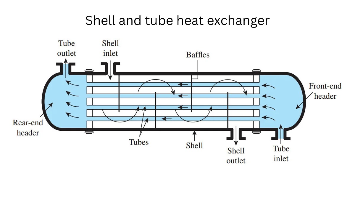
A shell and tube heat exchanger transfers thermal energy between two fluids without allowing them to mix. One fluid flows through a bundle of tubes while the other flows around those tubes inside a pressure-containing shell. This durable design serves power plants, refineries, chemical facilities, food processing, HVAC systems, pharmaceutical manufacturing, marine equipment, and many other industries.
Table of Contents
This evergreen guide explains how a shell and tube heat exchanger works, its main parts, flow arrangements, nine design principles, thermal calculations, pressure drop, materials, fouling, inspection, maintenance, and selection. For wider industrial context, visit our engineering and manufacturing guide, which connects heat transfer with power generation, HVAC, CFD, manufacturing, and process control.
What Is a Shell and Tube Heat Exchanger?
A shell and tube heat exchanger is a surface heat exchanger. Its tubes create a barrier between the process fluids while conducting heat from the hotter side to the colder side. The tube bundle provides a large transfer area within a compact pressure vessel. Headers or channel heads distribute tube-side flow, and nozzles connect the shell side to the process.
A shell and tube heat exchanger can handle a broad range of temperatures, pressures, flow rates, and fluid properties. Components can be manufactured from carbon steel, stainless steel, copper alloys, nickel alloys, titanium, duplex steels, or other compatible materials. The equipment can also be opened for inspection and cleaning when its mechanical arrangement permits.
How Does a Shell and Tube Heat Exchanger Work?
Heat moves through three linked mechanisms. Convection transfers energy from the hot fluid to the tube wall. Conduction carries energy through the tube material. Convection then transfers energy from the opposite wall to the cold fluid. Radiation is usually less important inside liquid-service exchangers but can matter in specialized high-temperature applications.
In a shell and tube heat exchanger, the two fluids may flow in parallel, countercurrent, crossflow, or a multipass combination. Countercurrent flow often provides a stronger temperature-driving force than parallel flow. Baffles direct shell-side fluid across the tubes, increase velocity, support the bundle, and limit vibration. The best shell and tube heat exchanger arrangement balances heat duty, pressure drop, fouling risk, mechanical integrity, and maintenance.
A shell and tube heat exchanger does not create heat. It recovers, removes, or redistributes energy already present in a process. Examples include condensing steam, cooling lubricating oil, heating feedwater, recovering reactor heat, evaporating a liquid, or cooling a product before storage.
Main Components and Their Functions
Shell
In a shell and tube heat exchanger, the shell is the outer pressure vessel containing the shell-side fluid. Its diameter accommodates the tube bundle and clearances needed for assembly and flow. Shell nozzles, supports, drains, vents, expansion provisions, and inspection openings depend on service and mechanical design.
Tubes and Tube Bundle
In a shell and tube heat exchanger, tubes provide most of the heat-transfer surface. Their outside diameter, wall thickness, length, pitch, layout, material, and surface condition affect thermal and mechanical performance. Tubes may be plain, finned, or otherwise enhanced. The complete bundle includes tubes, tube sheets, baffles, tie rods, spacers, and supporting parts.
Tube Sheets
Shell and tube heat exchanger tube sheets separate the fluids and anchor the tube ends. Tubes may be expanded, welded, or both. Joint selection depends on leakage risk, cyclic duty, corrosion, inspection, and applicable design requirements. Tube-sheet thickness must resist pressure and mechanical loads without excessive deformation.
Channel Heads and Covers
Shell and tube heat exchanger channel heads distribute tube-side fluid among tubes and passes. Removable covers give access for inspection, cleaning, plugging, or repair. Pass-partition plates route flow through multiple tube passes, raising velocity when the flow rate would otherwise be too low.
Baffles and Supports
Shell and tube heat exchanger baffles guide shell-side flow and support tubes against sagging and vibration. Segmental, double-segmental, helical, and specialized baffles produce different flow patterns. Baffle spacing and cut influence velocity, heat transfer, bypassing, pressure drop, and vibration risk.
Common Mechanical Configurations
Fixed Tube-Sheet Exchanger
Both tube sheets are fixed to the shell. This arrangement is relatively simple and economical, but differential thermal expansion creates stress unless temperatures and materials are suitable or an expansion joint is provided. Mechanical cleaning of the shell side can be difficult because the bundle is not removable.
U-Tube Exchanger
Each tube bends into a U shape and connects to one tube sheet. The bends accommodate thermal expansion, and the bundle can usually be removed. Cleaning the inside of tight bends is more difficult, and individual tubes cannot always be replaced as simply as straight tubes.
Floating-Head Exchanger
One end of the tube bundle can move relative to the shell. A floating-head shell and tube heat exchanger accommodates differential expansion and often allows mechanical cleaning on both sides. The advantages come with more components, seals, fabrication complexity, cost, and potential leakage points.
9 Powerful Design Principles
1. Define the Heat Duty Correctly
Shell and tube heat exchanger design begins with mass flow, inlet and required outlet temperatures, phase change, heat capacity, operating range, and uncertainty. Heat lost by the hot stream should approximately equal heat gained by the cold stream after legitimate environmental losses are considered. Incorrect process data cannot be repaired by sophisticated software.
2. Establish the Temperature Driving Force
Shell and tube heat exchanger heat transfer requires a temperature difference. Engineers commonly use the log-mean temperature difference for idealized parallel or countercurrent flow, then apply a correction factor for multipass arrangements. A temperature approach that is too small can require a very large surface area and may be impractical.
3. Select a Realistic Overall Heat-Transfer Coefficient
In a shell and tube heat exchanger, the overall coefficient combines tube-side convection, wall conduction, shell-side convection, and fouling resistances. It changes with fluid properties, velocity, phase, geometry, surface condition, and temperature. Preliminary values may come from experience, but final design requires calculation and appropriate margins.
4. Balance Heat Transfer and Pressure Drop
In a shell and tube heat exchanger, higher velocity usually improves heat transfer and reduces deposit formation, but it also raises pressure drop, pumping power, erosion, noise, and vibration. Low velocity saves pressure but may permit sedimentation or weak thermal performance. A good shell and tube heat exchanger design satisfies both thermal and hydraulic limits.
5. Assign Fluids to the Correct Side
High-pressure, corrosive, fouling, viscous, hazardous, or phase-changing fluids require deliberate side assignment. Putting high pressure inside smaller-diameter tubes can reduce pressure-containing material. A heavily fouling fluid may belong on the side that is easier to clean. Hazard, leakage consequence, metallurgy, inventory, and control also matter.
6. Choose Suitable Materials
Shell and tube heat exchanger materials must resist general corrosion, pitting, crevice corrosion, erosion, stress-corrosion cracking, embrittlement, temperature damage, and galvanic interactions. Compatibility with cleaning chemicals and start-up conditions matters as much as normal operation. Material certificates and positive identification may be required in critical service.
7. Control Thermal Expansion and Mechanical Loads
In a shell and tube heat exchanger, the shell and tubes may expand by different amounts because they have different temperatures, lengths, or materials. Fixed, U-tube, floating-head, or expansion-joint arrangements manage this movement. Designers also consider nozzle loads, weight, wind, seismic forces, transport, supports, vacuum, pressure cycles, and occasional conditions.
8. Design for Fouling and Cleaning
Inside a shell and tube heat exchanger, real process fluids deposit scale, sediment, biological material, corrosion products, polymers, coke, or other matter. Fouling lowers heat transfer and increases pressure drop. The design should consider fouling allowance, velocity, surface temperature, filtration, chemical treatment, bundle removal, cover access, rodding, hydroblasting, and safe chemical cleaning.
9. Prevent Vibration and Flow-Induced Damage
Shell-side crossflow can excite tubes through vortex shedding, turbulence, fluid-elastic instability, acoustic resonance, or two-phase forces. Unsupported span, baffle spacing, tube natural frequency, flow velocity, and damping influence risk. Vibration can wear tubes at supports and create leaks between the fluids.
Essential Thermal Calculations
The basic heat-duty relationship is Q = m × Cp × temperature change for a single-phase fluid when properties are reasonably constant. During boiling or condensation, latent heat becomes important. The required area is often estimated from Q = U × A × F × LMTD, where U is the overall coefficient, A is area, F is a correction factor, and LMTD is the log-mean temperature difference.
This equation looks simple, but its terms interact. Film coefficients depend on flow regime and geometry. Fluid properties change with temperature. Fouling evolves with time. Leakage and bypass streams reduce effective shell-side performance. Thermal design therefore requires iteration between area, velocities, pressure drop, configuration, and mechanical constraints.
For complex flow, two-phase service, unusual geometry, or performance troubleshooting, engineers may use specialized rating software and computational fluid dynamics. Models should be verified, validated, and checked against operating data rather than accepted as automatic truth.
Tube Layout, Passes, and Baffle Design
Triangular tube layouts fit more surface into a given shell diameter and promote turbulence, but cleaning lanes are limited. Square and rotated-square layouts can improve access for mechanical shell-side cleaning. Tube pitch must provide structural ligament, flow space, and fabrication clearance.
Multiple tube passes increase velocity but also add pressure loss and introduce pass-partition effects. Baffle cut controls the open flow window, while spacing affects crossflow velocity and unsupported length. Very close spacing may create excessive pressure drop; wide spacing can reduce transfer and increase vibration.
A shell and tube heat exchanger can suffer from bypassing between the bundle and shell, leakage through baffle clearances, and unequal flow distribution. Sealing strips, appropriate clearances, and careful mechanical design improve effective flow without creating assembly problems.
Condensers, Reboilers, Heaters, and Coolers
A condenser removes latent heat from vapor and converts it to liquid. Venting noncondensable gases is important because they reduce heat transfer and raise pressure. A reboiler adds heat to vaporize part of a liquid stream, commonly supporting distillation. Thermosiphon reboilers rely on density differences for circulation, while kettle designs provide a vapor space.
Heaters raise process temperature using steam, hot water, thermal oil, or another hot stream. Coolers reject heat to cooling water, air-linked circuits, chilled water, or refrigerant systems. Each duty changes fluid behavior, controls, relief scenarios, drainage, and start-up requirements.
Fouling: Causes, Effects, and Prevention
Fouling can result from crystallization, particulate deposition, chemical reaction, corrosion, biological growth, freezing, or coking. Deposits add thermal resistance, restrict flow, increase energy use, and create under-deposit corrosion. A falling outlet temperature or rising pressure drop may indicate deterioration, but instrumentation accuracy and changing process conditions must be checked first.
- Maintain velocities that discourage settling without causing erosion.
- Control water chemistry, filtration, and biological activity.
- Avoid surface temperatures that promote precipitation or degradation.
- Monitor approach temperature, duty, flow, and pressure drop.
- Provide access for the cleaning method selected.
- Analyze deposits to identify the true mechanism.
- Use operating data to optimize cleaning intervals.
Adding a large fouling factor is not always conservative. It may increase surface area, lower velocity, and create more fouling. The allowance should reflect service experience and an integrated design rather than a copied value.
Corrosion and Tube Failure
Tubes may fail through thinning, pitting, erosion-corrosion, vibration wear, fatigue, stress-corrosion cracking, fretting, galvanic attack, freezing, overheating, or improper cleaning. Leakage can contaminate product, damage downstream equipment, create a reaction, or release hazardous material.
Failure analysis should preserve evidence and examine location, morphology, deposits, material, operating history, water chemistry, vibration, and previous repairs. Plugging a tube can restore containment temporarily, but excessive plugging changes velocity and thermal performance. Repair or replacement criteria should be defined by engineering and integrity requirements.
Inspection and Condition Monitoring
Shell and tube heat exchanger inspection methods may include visual examination, pressure testing, leak testing, ultrasonic thickness measurement, eddy-current testing, remote-field testing, magnetic methods, dye penetrant, and tube-sampling analysis. Method selection depends on tube material, defect type, geometry, access, and required sensitivity.
Operating monitoring complements outage inspection. Track temperatures, flows, pressure drops, steam or cooling consumption, vibration, chemistry, and leakage indicators. Trending normalized performance is more informative than comparing raw temperatures under different loads.
Cleaning and Maintenance Methods
Mechanical cleaning may use brushes, scrapers, rotating tools, projectiles, or high-pressure water. Chemical cleaning dissolves or loosens selected deposits using a controlled solution. Online techniques may be possible in certain services. The method must be compatible with metallurgy, gaskets, coatings, waste treatment, and safety requirements.
Before opening a shell and tube heat exchanger, isolate, depressurize, drain, vent, cool, purge, test, and apply required energy controls. Residual liquid may be trapped behind valves or tube blockages. Covers and channel heads are heavy components requiring planned lifting and controlled bolting.
After maintenance, inspect sealing surfaces, install correct gaskets, control bolt tightening, restore instruments, remove foreign material, and perform required leak or pressure tests. Record plugged tubes, measured thickness, deposits, repairs, and changed configuration for future decisions.
Standards, Codes, and Documentation
Pressure design, fabrication, examination, testing, and repair must follow applicable laws and codes. Industry projects commonly reference pressure-vessel codes and purchaser specifications. The Tubular Exchanger Manufacturers Association publishes widely used mechanical standards and nomenclature for shell-and-tube equipment.
Documentation may include data sheets, thermal calculations, mechanical drawings, material certificates, welding records, examination reports, pressure tests, relief evaluations, operating instructions, inspection plans, and repair history. The governing requirements depend on location, service, owner, and contract.
Applications in Power Plants and HVAC
In a thermal power plant, shell-and-tube equipment may serve as condensers, feedwater heaters, oil coolers, closed-loop cooling exchangers, and process heaters. Reliability directly affects turbine performance, water chemistry, auxiliary systems, and generation efficiency.
In large HVAC and district-energy systems, shell-and-tube units may act as evaporators, condensers, water heaters, or isolation exchangers. Our guide to understanding HVAC explains how heat exchangers fit into heating, cooling, ventilation, controls, and indoor-comfort systems.
How to Select the Right Exchanger
- Confirm normal, minimum, maximum, start-up, shutdown, and upset conditions.
- Define heat duty and permitted outlet temperatures.
- Set allowable pressure drops on both sides.
- Characterize composition, phase, viscosity, solids, corrosivity, and fouling.
- Identify design pressure, temperature, vacuum, and cyclic conditions.
- Determine required metallurgy and corrosion allowance.
- Choose cleaning access and bundle-removal space.
- Evaluate differential expansion and vibration.
- Confirm code, inspection, documentation, and spare-part requirements.
- Compare life-cycle energy, maintenance, reliability, and capital cost.
The lowest purchase price is not necessarily the lowest total cost. A slightly larger or more maintainable shell and tube heat exchanger can reduce downtime, pumping power, cleaning difficulty, and early replacement. Conversely, unnecessary area and exotic metallurgy add cost without guaranteed benefit.
Common Design and Operating Mistakes
- Using inaccurate or single-point process data.
- Ignoring start-up, shutdown, turndown, or future operating cases.
- Selecting fouling factors without considering velocity.
- Exceeding available pump or compressor pressure.
- Ignoring thermal expansion and nozzle loads.
- Providing no practical cleaning or bundle-removal access.
- Underestimating vibration and two-phase instability.
- Choosing materials from general corrosion rate alone.
- Failing to vent gases or drain liquids.
- Evaluating performance from uncorrected temperatures.
Frequently Asked Questions
Why are baffles used?
Baffles direct shell-side flow across tubes, support the bundle, increase velocity, improve heat transfer, and control unsupported tube length. Poor baffle design can cause high pressure drop, bypassing, or vibration.
Which fluid should go through the tubes?
The decision depends on pressure, corrosion, fouling, viscosity, hazard, phase change, flow rate, cleaning, inventory, and metallurgy. High-pressure or heavily fouling fluid is often placed in tubes, but there is no universal rule.
What causes low heat-exchanger performance?
Common causes include fouling, low flow, air or gas binding, bypassing, incorrect valve position, damaged baffles, plugged tubes, changed fluid properties, instrument error, and duty beyond the original design.
Can shell and tube exchangers handle phase change?
Yes. They are widely used as condensers, evaporators, and reboilers. Phase-change design requires attention to distribution, drainage, pressure drop, noncondensable gases, circulation, and control.
How often should an exchanger be cleaned?
The interval should be based on deposit mechanism, performance trend, pressure drop, inspection, production risk, and cleaning economics. Fixed schedules are useful initially, but condition-based planning can avoid both unnecessary cleaning and severe fouling.
Final Thoughts
A shell and tube heat exchanger succeeds when thermal performance, hydraulics, metallurgy, mechanical integrity, fouling control, inspection, and maintenance are designed as one system. Extra surface area alone cannot compensate for poor flow distribution, unsuitable materials, inaccessible cleaning, or vibration.
Begin with reliable process data, evaluate the full operating envelope, and verify performance with measurements over the equipment lifecycle. Return to our engineering and manufacturing guide for related explanations of power plants, HVAC, CFD, manufacturing, automation, and industrial reliability.
